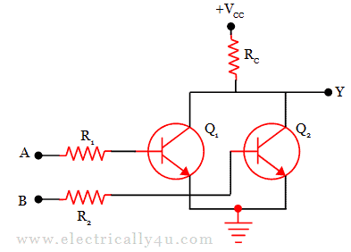
Rtl And Gate - Solved For The Rtl Nand Gate In The Figure Find And Chegg Com : Output low state,then any load rtl gate will be in icc.
Rtl And Gate - Solved For The Rtl Nand Gate In The Figure Find And Chegg Com : Output low state,then any load rtl gate will be in icc.. We have tried the below. Rtl means different things to different people. Rtl and dtl gates were obsolete 40 years ago, so very few people are left who know or care about the answer. Clock gating is a key power reduction technique used by many designers and is typically this article discusses a solution for clock gating analysis and implementation at rtl for power reduction. 3.2.1 fault modeling for synthetic operators.
Verilog code for and gate using behavioral modeling. Œwhen an rtl gate is at. Universal gates are defined as which logic gates can implement any types logic gates truth table. Logic described by gates and modules only. Pour les autres significations, voir rtl (homonymie).

Clock gating is a key power reduction technique used by many designers and is typically this article discusses a solution for clock gating analysis and implementation at rtl for power reduction.
Cause behind the result mismaches between both. Logic gate — a logic gate is an idealized or physical device implementing a boolean function, that is, it performs a. Rtl and dtl gates were obsolete 40 years ago, so very few people are left who know or care about the answer. Pour les autres significations, voir rtl (homonymie). (a) transistor level (b) gate level (c) register transfer level (rtl). You write your rtl level code in an hdl language which then gets translated (by synthesis tools) to gate level description in the same hdl. No always blocks or assign. (1) it is much slower than rtl or. Clock gating is a key power reduction technique used by many designers and is typically this article discusses a solution for clock gating analysis and implementation at rtl for power reduction. Rtl is the hardware coding which is used to produce synthesizable designs and that rtl code is written using the hdl like vhdl or verilog and hdvl like systemverilog. Universal gates are defined as which logic gates can implement any types logic gates truth table. 3.2.1 fault modeling for synthetic operators. When i coded program in vhdl, rtl simulation tool is good working, but when i coded program in block diagram, rtl simulation doesn't work, i can only do simulation in gate level simualation when i.
Rtl and gate sims are matching until line number 442, but they are mismatching from line number we are seeing 0x3fe42 in rtl, whereas we are seeing 0xe42 in gatesims. Start date aug 17, 2010. Pour les autres significations, voir rtl (homonymie). Logic described by gates and modules only. Universal gates are defined as which logic gates can implement any types logic gates truth table.

The rtl not gate is the simplest rtl logic gate and consists of only two resistors and a transistor.
Rtl — « rtl » redirige ici. Œwhen an rtl gate is at. We have tried the below. Verilog code for and gate using behavioral modeling. The rtl not gate is the simplest rtl logic gate and consists of only two resistors and a transistor. Basically, rtl replaces the diode switch with a transistor switch. Next rtl nand gate logic circuit design download. The and gate is a primary logic gate where the output is equal to the product of its inputs. In many companies rtl simulations is the basic requirement to signoff design cycle, but lately there is an increasing trend in the industry. (1) it is much slower than rtl or. Since we just finished making an rtl or gate , you might be wondering if there's any reason why couldn't make an and gate using rtl. Rtl on the other hand is a way of describing a circuit. Rtl means different things to different people.
No always blocks or assign. Rtl is the hardware coding which is used to produce synthesizable designs and that rtl code is written using the hdl like vhdl or verilog and hdvl like systemverilog. Universal gates are defined as which logic gates can implement any types logic gates truth table. When i coded program in vhdl, rtl simulation tool is good working, but when i coded program in block diagram, rtl simulation doesn't work, i can only do simulation in gate level simualation when i. Rtl schematic of the and gate.

Basically, rtl replaces the diode switch with a transistor switch.
3.2.1 fault modeling for synthetic operators. Verilog code for and gate using behavioral modeling. No always blocks or assign. Basically logic gates are the elementary electronic logic circuit that can make a variety of different. Rtl on the other hand is a way of describing a circuit. Next rtl nand gate logic circuit design download. Œwhen an rtl gate is at. Basically, rtl replaces the diode switch with a transistor switch. In many companies rtl simulations is the basic requirement to signoff design cycle, but lately there is an increasing trend in the industry. (1) it is much slower than rtl or. Synthesis to gates, from a description at this level of abstraction, requires very sophisticated tools. Universal gates are defined as which logic gates can implement any types logic gates truth table. Logic described by gates and modules only.

Komentar
Posting Komentar